
We went over the basics of Kubernetes here. Lets have a look at using it to implement a very simple three tier application.
- Tier 1 – the sender: calls the tier-2 URL every few seconds – an HTTP Post of a short, plain-text message.
- Tier 2 – the relay: listens for HTTP calls (from tier-1) and passes them on to another HTTP server (tier-3)
- Tier 3 – the sink: also listens for HTTP calls (tier-2) and logs the message received
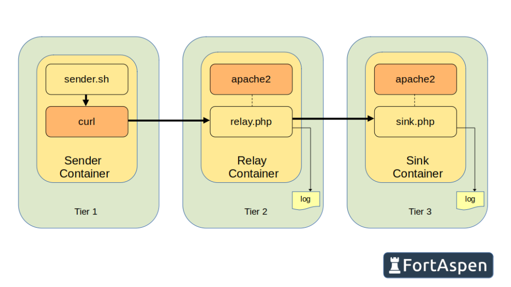
To make it a little bit more “Kubernetes” we’ll implement three instances of tier 1, two instances of tier 2 and three instances of tier 3.
As we’re implementing this in Kubernetes each of the tiers must be implemented in OCI-compliant containers. Here we’ll use Podman for the development and build but the process for Docker would be identical.
(You can check out our guides for installing Kubernetes with the different container managers: containerd, Docker, CRI-O)
Building Containers
Tier 1
The sender is a simple shell script.
#!/bin/bash
ip4=`hostname -I`
while true
do
  msgText="Message sent from $ip4 on `date`"
  echo "********  Sending $msgText"
  curl -X POST -H "Content-Type: text/plain" -s -d "$msgText" $RELAY_URL
  echo
  sleep 5
done
First we get the local IP address (“hostname -I”) and then enter an infinite loop. On each iteration of the loop a message “Message send from <ip address> on <timestamp>” is formatted and then sent via an HTTP post to the URL held in the environment variable “RELAY_URL”. The process ‘sleeps’ for 5 seconds before starting the loop again and formatting the next message.
Next we create the container image so we need a Containerfile (or Dockerfile).
Ctr1We start with the basic Alpine Linux image and install curl and the script. The container’s main command is set to be the script above which will start running as soon as the container is active.
Call the Podman build command to process the containerfile in the ~/sendCtr directory.
podman build -t sender ~/sendCtr
podman image ls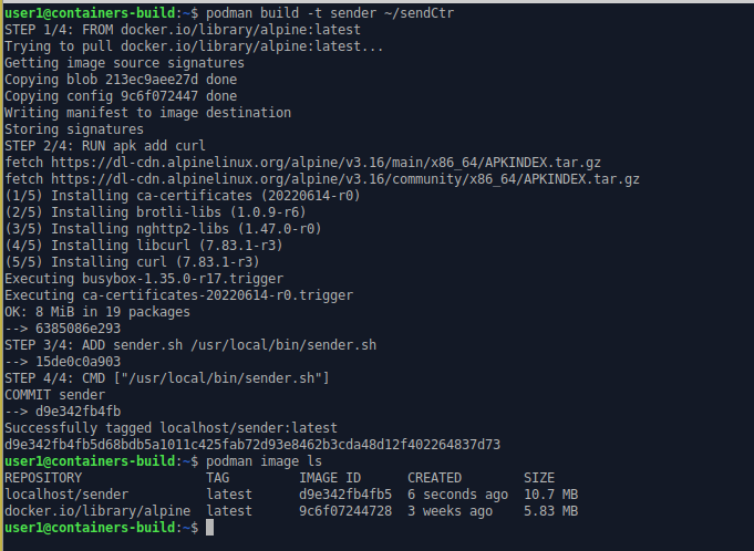
Tier 2
The tier 2 relay processing is implemented as a PHP page running within an Apache2 web server.
<?php
# Retreive the data POSTed to this URL
$msgContent = file_get_contents('php://input');

# Open a file on the host and save the message being relayed
define("OUT_FILE", "/var/local/container/Relay_".gethostbyname(gethostname()).".txt");
$theFile = fopen(OUT_FILE, "a") or die("Unable to open file!");
fwrite($theFile, "Relaying from ".$_SERVER['REMOTE_ADDR']." at ".date("Y-m-d h:i:sa")." : ".$msgContent."\n");
fclose($theFile);

# Use PHP curl to send the arriving message to the "Sink"
$ch = curl_init( $SINK_URL );
curl_setopt( $ch, CURLOPT_POST, 1);
curl_setopt( $ch, CURLOPT_POSTFIELDS, $msgContent);
curl_setopt( $ch, CURLOPT_FOLLOWLOCATION, 1);
curl_setopt( $ch, CURLOPT_HEADER, 0);
curl_setopt( $ch, CURLOPT_RETURNTRANSFER, 1);

$response = curl_exec( $ch );

# Return the response from the sink to the client
header('Content-Type: text/plain');
echo $response;
#echo "Logged message from ".$_SERVER['REMOTE_ADDR'];
?>
Like the Tier 1 sender script, the PHP page gets its target URL from an environment variable. It then retrieves the arriving message content and logs it to a local file (the filename includes the local IP address so multiple instances with different IP addresses can operate at the same time). A PHP curl request is formatted and executed to send the arriving message on to tier 3. Finally any message returned by Tier 3 is then returned to the calling Tier 1 process as plain text.
We create a Containerfile to create a container image that has a PHP service running under an Apache2 web server. This time we create a local directory for the log file and make it available for mapping outside the container by declaring a volume. TCP port 80 is also “exposed” so it can be accessed from outside the container.
ctr 2The Podman build command processes the containerfile in the ~/relayCtr directory to create the “relay” container image.
podman build -t relay ~/relayCtr
podman image ls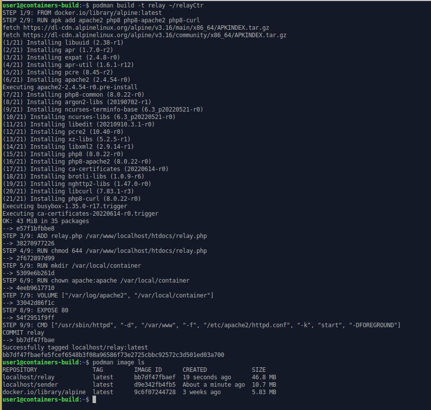
Tier 3
The third tier is very similar to Tier2 but it only logs arriving messages in a file.
<?php
# Retreive the data POSTed to this URL
$msgContent = file_get_contents('php://input');

# Open a file on the host and save the posted message
define("OUT_FILE", "/var/local/container/Sink_".gethostbyname(gethostname()).".txt");
$theFile = fopen(OUT_FILE, "a") or die("Unable to open file!");
fwrite($theFile, "From ".$_SERVER['REMOTE_ADDR']." at ".date("Y-m-d h:i:sa")." : ".$msgContent."\n");
fclose($theFile);

# Return a simple message to the client
header('Content-Type: text/plain');
echo "Logged message from ".$_SERVER['REMOTE_ADDR'];
?>
The containerfile and build process is also very similar.
ctr 3This time the container image is labelled “sink”.
podman build -t sink ~/sinkCtr
podman image ls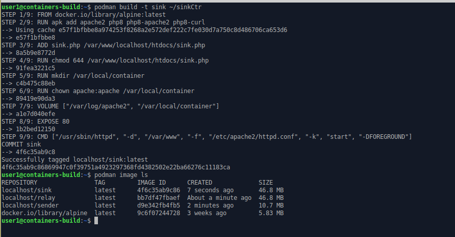
Upload To Registry
Next we have to make the sender, relay and sink container images available to Kubernetes. When the Kubernetes control-plane gives an instruction to a node to start a pod, where will it get the images from?
One option is to manually load each container image from file into the local container runtime on every node. This is prone to failure. Whenever a new new node is added you have to remember to manually pull the image into the container runtime. New versions of the container image will need a manual upload on every Kuberntes node.
The preferred method is to upload the files to a container registry and let Kubernetes retrieve them from there. No need to create image files, move them around or log in to individual nodes. It does however mean you need access to a image registry. You could use the Docker hub, the container registry of a cloud provider like AWS, Azure or Google Cloud or you can host your own. Here we are using an instance of the Harbor registry running on a local VM (you can see how to set up a Harbor container registry here). The registry is set up to have domain name ‘registry.fortaspen.com’ and we use the default “library” project. To send the images from the build machine to the registry we have to “tag” the images with a name that points to the remote registry
podman images ls
podman tag localhost/sender registry.fortaspen.com/library/sender
podman tag localhost/relay registry.fortaspen.com/library/relay
podman tag localhost/sink registry.fortaspen.com/library/sink
podman images ls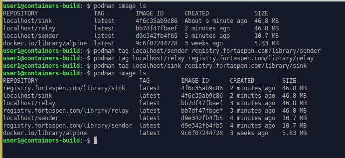
Next we have to connect podman to our remote Harbor registry:
podman login registry.fortaspen.com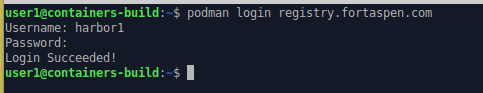
and then push the images from the podman host to the registry using the push command.
podman push registry.fortaspen.com/library/sender
podman push registry.fortaspen.com/library/relay
podman push registry.fortaspen.com/library/sink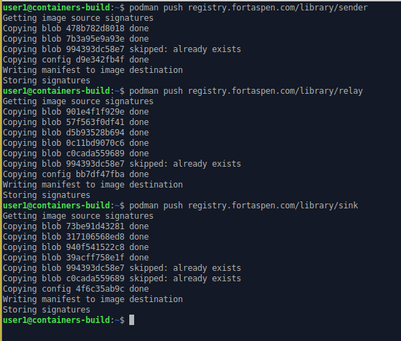
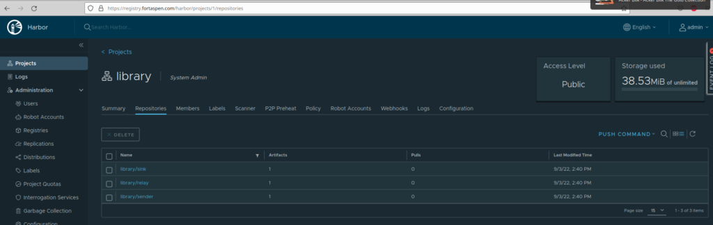
The images are now available in the harbor repository.
Dormant Kubernetes
The Kubernetes cluster we’ll be using has three nodes: the control-plane/master node (kube-master) and two worker nodes (kube-node1 and kube-node2). We can use the kubectl command on the control-plane node to see what is going on.
kubectl get nodes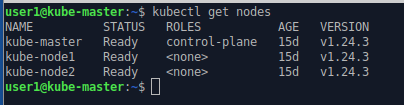
Each of the nodes has a kubelet running as a service to oversee the operation on that server.
systemctl status kubelet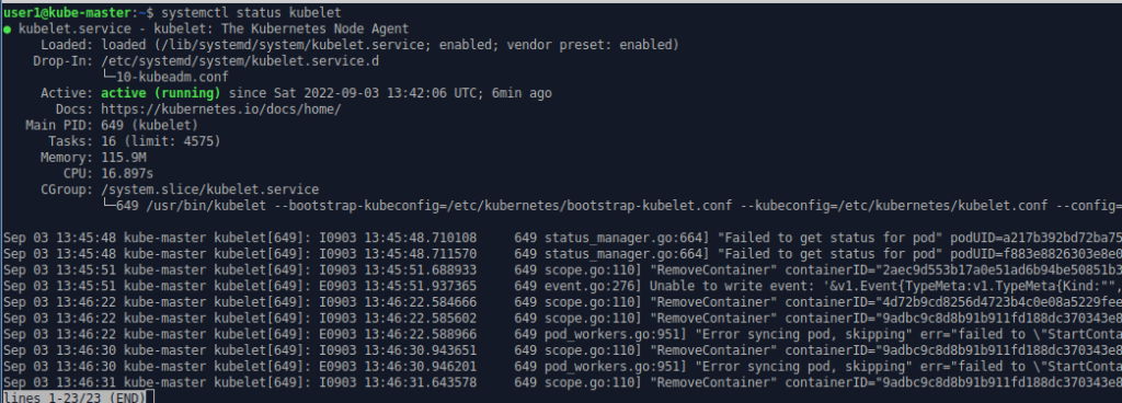
No pods are running in the default namespace. There have not been any application requests issued yet.
nodectl get pods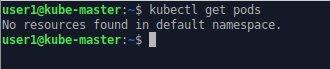
but if we ask for the list of pods in all namespaces, the kubernetes system pods become visible. By adding the “-o wide” option we get mode detail including which node the pod is running on.
Nodectl get pods –all-namespaces
Nodectl get pods –all-namespaces -o wide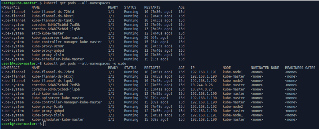
| kube-master | kube-node1 | kube-node2 | |
| Api Server | ✔ | ||
| Controller Manager | ✔ | ||
| Scheduler | ✔ | ||
| etcd | ✔ | ||
| coreDNS | ✔ | ||
| Proxy | ✔ | ✔ | ✔ |
| Flannel Networking | ✔ | ✔ | ✔ |
As you can see the control-plane processes are running on one node.
When we issue kubectl commands, the kubectl executable communicates with the API server pod on the master node via TCP port 6443. Kubectl needs configuration to authenticate with the API server which is found in a file (The default file location is ~/.kube/config but it can be overridden by setting the environment variable KUBECONFIG to the location of the file).
Link To Registry
To read container images from a remote registry you first need to tell Kubernetes the connection details for that registry. This is done by creating a Kubernetes “secret” with the connection credentials. You can then refer to that secret when you configure pods. A secret is a Kubernetes object that holds confidential information. It is intended as a one way process: there are no tools to extract the confidential information from Kubernetes once the secret has been created.
To create a secret that holds the login information for our Harbor registry.
kubectl create secret docker-registry regcred --docker-server=registry.fortaspen.com --docker-username=harborUser --docker-password=myPassword --docker-email=notanemail@gmail.com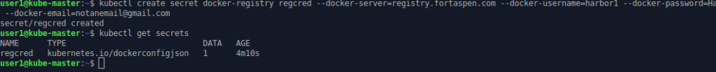
(Note that the secret type and options are “docker-” even though we are not dealing with a Docker registry.)
Once created we can refer to secret “regcred” when registry credentials are needed.
Kubernetes Configuration
So we’ve build our application containers and loaded them into a registry. We got a working Kubernetes cluster and added a “secret” to allow Kubernetes to extract the containers from that registry. Now it’s time to start configuring the application. First we create the Kubernetes services (network placeholders) to allow different tiers of the application to communicate with each other. We look quickly at pods before creating multi-pod “deployments” for each of the tiers.
Services
In the scenario outlined at the top of the page
- the sender needs to communicate with the relay and
- the relay needs to communicate with the sink.
How does the sender know where the relay is? The answer is it uses “service” placeholders as an intermediary. In our example we create a “relay-svc” service placeholder to allow other pods to link to the relay pods wherever they are running. On creation “relay-svc” becomes visible in the Kubernetes internal DNS system. In our example. the sender container can send TCP messages to “relay-svc” and, using DNS look ups, they are routed to a relay pod.
The full name of the relay-svc service is
relay-svc.default.svc.cluster.local
- “cluster.local” is, unsurprisingly, the default DNS name for the local cluster.
- “svc” is the Kubernetes services on that cluster
- “default” is the namespace (“default” unless specified)
- “relay-svc” is the short-name of the service.
But in simple scenarios “relay-svc” on its own works just as well.
The relay pods are linked to the relay service using “labels”. Labels are a construct used across Kubernetes to link entities. In our example, when the relay pod is defined it is allocated two tags:
- app=3-level-demo
- role=relay
We can then define the Kubernetes service “relay-svc” that uses the same labels as a “selector”. When pods are created with these labels they become a target for the service. When pods with these labels are removed they are automatically removed from the service targets.
Labels are a means of loosely coupling entities in Kubernetes. This allows the system to continue to operate as entities come and go. Care must be taken however. There is nothing to stop you accidentally defining a set of pods called “oops” with the same labels and a wholly unrelated purpose. Some of the messages sent to the “relay-svc” would then be routed to the “oops” pods.
Configuration can be supplied to Kubernetes in a number of formats. The most common format is yaml. Here is the configuration for our relay service.
apiVersion: v1
kind: Service
metadata:
  name: relay-svc
spec:
  type: NodePort
  selector:
    app: 3-level-demo
    role: relay
  ports:
  - name: relay-port
    protocol: TCP
    port: 80
    targetPort: 80
    nodePort: 30100
This follows the standard top level configuration items.
- apiVersion – the API version being used in the definition
- kind – the Kubernetes object type: Service
- metadata – fields identifying the object, includes the name but can include namespace
- spec – the detail of the object being defined
Here the spec includes the selector (specifying the labels to use finding the target pods) and the port to be mapped.
We pass this configuration file into the Kubernetes cluster using kubectl.
kubectl apply -f relay-svc.yaml
kubectl get services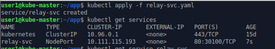
We can also configure the sink service. This gives the relay somewhere to send the messages it receives.
apiVersion: v1
kind: Service
metadata:
  name: sink-svc
spec:
  type: NodePort
  selector:
    app: 3-level-demo
    role: sink
  ports:
  - name: sink-port
    protocol: TCP
    port: 80
    targetPort: 80
    nodePort: 30200
kubectl apply -f sink-svc.yaml
kubectl get services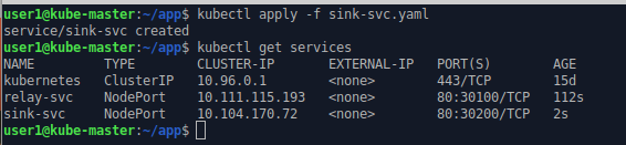
Pods
Neither sink-svc nor relay-svc are much use at the moment because there are no application pods running. Next we need to create pods so that the pod labels match-up to service labels and the service can start to pass messages to pods.
We set up our application using more advance constructs in a moment but if you wanted to create a single pod to act as a sink you could apply the following yaml file to Kubernetes.
apiVersion: v1
kind: Pod
metadata:
  name: sinkpod
  labels:
    app: 3-level-demo
    role: sink
spec:
  containers:
  - name: sink
    image: registry.fortaspen.com/library/sink
    ports:
      - containerPort: 80
    volumeMounts:
    - name: applog
      mountPath: /var/local/container
  imagePullSecrets:
  - name: regcred
  volumes:
  - name: applog
    hostPath:
      path: /var/local/app
      type: Directory
kubectl apply -f podExample.yaml
kubectl get pods -o wide
kubectl describe sinkpod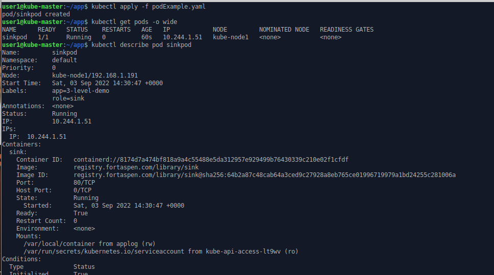
we can see a container has been created inside the pod based on image ‘registry.fortaspen.com/library/sink’. This is listening inside the container on TCP port 80.
Kubernetes spots that the labels on the new pod match up with those in the sink-svc service definition and it links the two by creating a new entity: an “endpoint”. The term endpoint is perhaps a little ambiguous. Within Kubernetes it is the list of the pods linked to a service (with the relevant network ports). It is managed internally. It is not something that is defined or managed by the user but it gives an indication that the pod/service link has been spotted.
kubectl get services
kubectl get endpoints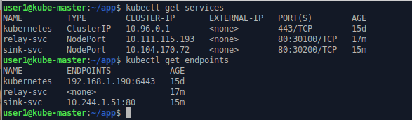
We can stop the pod by deleting the entity within Kubernetes. Kubernetes spots that there is now no pod with matching labels of the sink-svc service and it deletes the endpoints.
kubectl delete pod sinkPod
kubectl get endpoints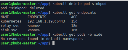
ReplicaSets & Deployments
Defining individual pods does not make the best use of Kubernetes features. It would give you few benefits over starting containers within a container manager like Docker or Podman. To let Kubernetes orchestrate your workload you need to start using ReplicaSets and deployments.
A Kubernetes ReplicaSets is a group of pods based on the same underlying container image that do the same job. In our example we want three sink containers to be active at once so we want a single ReplicaSets with three “replicas”.
Just like we created the single pod directly, you can create a ReplicaSets directly. However in a production environment you do not want to do this. You should use a supervisory object, a deployment, that does that job for you.
Why would you want an additional layer of definition? Because deployments help with the management of software updates and upgrades.
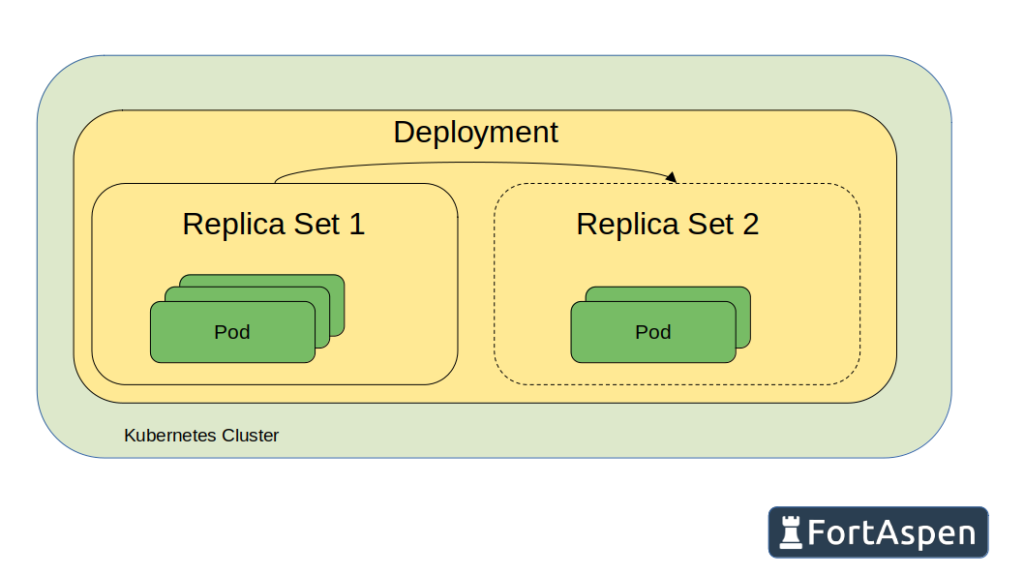
The deployment is a long-lived definition of the desire for a number of pods to be active. When a deployment definition is created in Kubernetes, a single ReplicaSet is created which in turn creates the required number of pods. When the time comes to switch to an updated container image, the deployment object is updated in Kubernetes, this creates a second ReplicaSet. The pods in the original ReplicaSet are gradually rolled-out and new pods, with the updated container image, rolled-in to the second ReplicaSet. At the end of the process the original ReplicaSet is empty and is destroyed and the new ReplicaSet has a full set of running pods using the updated container image.
To create the deployment for the 3 pods running the sink container we can apply the following yaml file.
apiVersion: apps/v1
kind: Deployment
metadata:
  name: sinks
  labels:
    app: 3-level-demo
    role: sink
spec:
  replicas: 3
  selector:
    matchLabels:
      app: 3-level-demo
      role: sink
  template:
    metadata:
      labels:
        app: 3-level-demo
        role: sink
    spec:
      containers:
      - name: sink
        image: registry.fortaspen.com/library/sink
        ports:
          - containerPort: 80
        volumeMounts:
        - name: applog
          mountPath: /var/local/container
      imagePullSecrets:
      - name: regcred
      volumes:
      - name: applog
        hostPath:
          path: /var/local/app
          type: Directory
The labels in the metadata section (metadata.labels) apply to the top-level deployment object itself and could be omitted for our scenario. The selector labels (spec.selector.matchlabels) are used to determine what pods are part of the deployment. Any pods with these labels that are running when the deployment is created will be adopted. The labels specified within the template section (spec.template.metadata.labels) are the labels that are applied to new pods created by the deployment and, for the deployment to function, must match those in the selector.
The template section (spec.template) defines the make up of each pod. The name of the pods will start with “sink”, use the image ‘registry.fortaspen.com/library/sink’ and expose network port 80. We have to specify the Kubernetes secret that holds the credentials for the registry that holds the container image.
kubectl apply -f sink.yaml
kubectl get deployments
kubectl get replicasets
kubectl get pods -o wide
kubectl get endpoints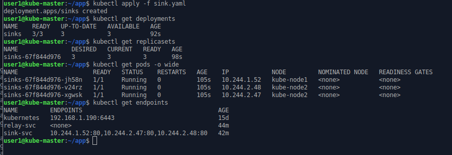
The name of the deployment is as defined in the configuration. The replica set may be replaced in time (i.e. when an upgrade is required) so its name is the deployment’s name and a unique ID. The name of the pods is the name of the replica set with another unique ID as suffix.
In general Kubernetes tries to avoid scheduling pods on the control plane/master nodes. Here the new pods have been spread over the two worker nodes (kube-node1 & kube-node2).
We can see that the selector labels of the sink-svc service have been spotted in the new pods created by the replica set and these new pods have been added to the list of endpoints for the service. The three pods are now ready to receive requests on the sink-svc service.
Next we create the relay deployment.
apiVersion: apps/v1
kind: Deployment
metadata:
  name: relays
spec:
  replicas: 2
  selector:
    matchLabels:
      app: 3-level-demo
      role: relay
  template:
    metadata:
      labels:
        app: 3-level-demo
        role: relay
    spec:
      containers:
      - name: relay
        image: registry.fortaspen.com/library/relay
        env:
        - name: SINK_URL
          value: "sink-svc/sink.php"
        ports:
          - containerPort: 80
        volumeMounts:
        - name: applog
          mountPath: /var/local/container
      imagePullSecrets:
      - name: regcred
      volumes:
      - name: applog
        hostPath:
          path: /var/local/app
          type: Directory
The relay deployment is similar to the sink deployment. There are only two replicas so there will be only two pods. The role label is obviously “relay” rather than “sink”. We need to set an environment variable “SINK_URL” on the pods so the process knows where to send the messages that arrive. This is where we use the Kubernetes service “sink-svc”. When the container process asks for a DNS look-up of “sink-svc” Kubernetes will return one of the endpoints associated with the service.
kubectl apply -f relay.yaml
kubectl get deployments
kubectl get replicasets
kubectl get pods
kubectl get endpoints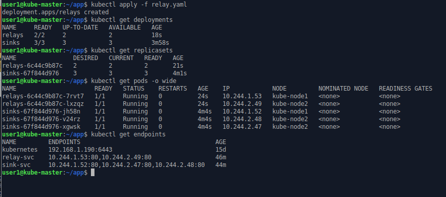
Note how the IP address of the endpoints match up to the IP address of the relevant pods. Remember each pod is allocated its own unique IP address.
Finally we create the sender deployment.
apiVersion: apps/v1
kind: Deployment
metadata:
  name: senders
spec:
  replicas: 3
  selector:
    matchLabels:
      app: 3-level-demo
      role: sender
  template:
    metadata:
      labels:
        app: 3-level-demo
        role: sender
    spec:
      containers:
      - name: sender
        image: registry.fortaspen.com/library/sender
        volumeMounts:
        - name: applog
          mountPath: /var/local/container
        env:
        - name: RELAY_URL
          value: "relay-svc/relay.php"
      imagePullSecrets:
      - name: regcred
      volumes:
      - name: applog
        hostPath:
          path: /var/local/app
          type: Directory
There are three pods in the sender deployment with role “sender”. The target of the messages is held in environment variable “RELAY_URL” (that is environment variable within the pod/container).
kubectl apply -f sender.yaml
kubectl get deployments
kubectl get replicasets
kubectl get pods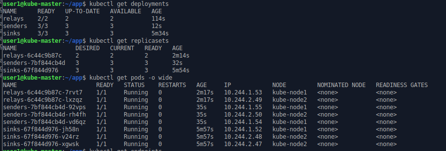
Once the sender pods start work, messages are send from sender to relay to sink. The sender script writes messages to “standard out”. This captured in the pod/container log and can be accessed by the kubectl log command
kubectl log sender-xxx-xxx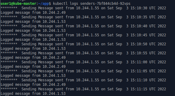
The IPs listed are those of sender and relay pods.
The relay and sink write their log to a local (inside their container) file which is mapped to the local host filesystem (/var/local/app directory).
On one of the hosts (kube-host1) we can look at a couple of the log files one for relay processes and one for sink processes
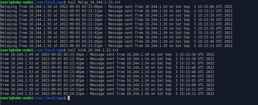
The sender pods issue HTTP requests to the Kubernetes service “relay-svc” which, based on label matching, routes the messages to one of the relay pods. The targeted pod is not fixed and can change with each call (basic load balancing). The relay pod sends the message on to a sink pod via the Kubernetes service “sink-svc” which logs the incoming message to a local file inside the container which is mapped in Kubernetes to a directory on host filesystem.